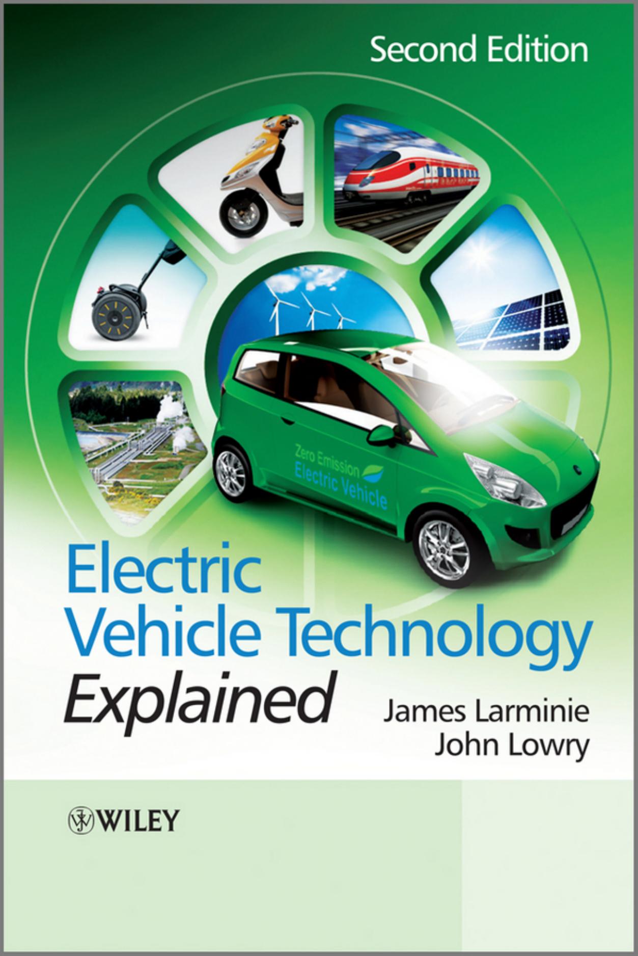
Electric Vehicle Technology Explained by James Larminie & John Lowry

Author:James Larminie & John Lowry
Language: eng
Format: epub, pdf
Publisher: Wiley
Published: 2012-07-06T04:00:00+00:00
7.1 The ‘Brushed’ DC Electric Motor
7.1.1 Operation of the Basic DC Motor
Electric vehicles use what can seem a bewildering range of different types of electric motors. However, the simplest form of electric motor, at least to understand, is the ‘brushed’ DC motor. This type of motor is very widely used in applications such as portable tools, toys, electrically operated windows in cars, and small domestic appliances such as hair dryers, even if they are AC mains powered.1 However, it is also still used as a traction motor, although the other types of motors considered later in this chapter are becoming more common for this application. The brushed DC motor is a good starting point because, as well as being widely used, most of the important issues in electric motor control can be more easily explained with reference to this type of motor.
The classical DC electric motor is shown in Figure 7.1. It is a DC motor, equipped with permanent magnets and brushes. This simplified motor has one coil, and the current passing through the wire near the magnet causes a force to be generated in the coil. The current flows through brush X, commutator half ring A, round the coil, and out through the other commutator half ring B and brush Y (XABY). On one side (as shown in the diagram) the force is upwards, and on the other it is downwards, because the current is flowing back towards the brushes and commutator. The two forces cause the coil to turn. The coil turns with the commutator, and once the wires are clear of the magnet the momentum carries it on round until the half rings of the commutator connect with the brushes again. When this happens the current is flowing in the same direction relative to the magnets, and hence the forces are in the same direction, continuing to turn the motor as before. However, the current will now be flowing through brush X, half ring B, round the coil to A and out through Y, so the current will be flowing in the opposite direction through the coil (XBAY).
Figure 7.1 Diagram to explain the operation of the simple permanent magnet DC motor
Download
Electric Vehicle Technology Explained by James Larminie & John Lowry.pdf
This site does not store any files on its server. We only index and link to content provided by other sites. Please contact the content providers to delete copyright contents if any and email us, we'll remove relevant links or contents immediately.
| Automotive | Engineering |
| Transportation |
Machine Learning at Scale with H2O by Gregory Keys | David Whiting(4282)
Never by Ken Follett(3919)
Urban Outlaw by Magnus Walker(3380)
OPNsense Beginner to Professional by Julio Cesar Bueno de Camargo(3275)
Sapiens and Homo Deus by Yuval Noah Harari(3051)
Will by Will Smith(2891)
A Short History of Nearly Everything by Bryson Bill(2675)
Hooked: A Dark, Contemporary Romance (Never After Series) by Emily McIntire(2537)
Rationality by Steven Pinker(2340)
Borders by unknow(2297)
The Becoming by Nora Roberts(2178)
Holy Bible (NIV) by Zondervan(2106)
HBR's 10 Must Reads 2022 by Harvard Business Review(1828)
A Short History of War by Jeremy Black(1827)
The One Percenter Encyclopedia by Bill Hayes(1816)
Freedom by Sonny Barger(1790)
Go Tell the Bees That I Am Gone by Diana Gabaldon(1743)
Five Ways to Fall by K.A. Tucker(1729)
Girls Auto Clinic Glove Box Guide by Patrice Banks(1718)
